The FET pattern: data source, data gate, data drain
Name, Intent
The FET components are designed to unify the querying and distributing of parameters. An object that provides a data source interface can be asked for parameters. Chaining data sources results in cascaded asking for parameters, thereby making it possible to delegate the querying of parameters. An object that provides a data drain interface can be given parameters. A data gate is used if parameters have to be distributed from a data source to one or more data drains. Parameters are given in form of Parameter Pot (PP).
The FET pattern is named according to a Field Effect Transistor which consists of source, gate and drain.
Motivation
A command needs some parameters. They should be provided through a dialog. The dialog has some preset data from its last use.
The following components take part in this scenario:
Preset Parameter Pot (PPP)
Dialog
Data Gate (DG)
Command Parameter Pot (CPP)
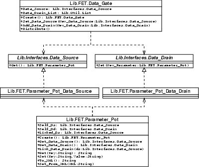
The Preset Parameter Pot (PPP), the Command Parameter Pot (CPP) and the dialog provide a data source interface. The Preset Parameter Pot (PPP) and the Command Parameter Pot (CPP) provide a data drain interface. The Preset Parameter Pot (PPP) is put in then dialog's data source property. The dialog is put in the DG's data source property. The Parameter Pot (PP) and Command Parameter Pot (CPP) are put in the DG's data drains property.
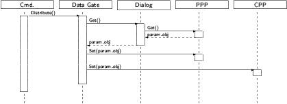
The DG gets a method call distribute. Then the DG asks the dialog for parameters. Then the dialog asks the Preset Parameter Pot (PPP) for parameters. The dialog gets some parameters, shows a window and lets the user modify them. After the user closes the window, the dialog returns the parameters to the DG. Now the DG distributes the parameters to the Preset Parameter Pot (PPP) and Command Parameter Pot (CPP).
Applicability
Use the FET pattern
to abstract from the real source of parameters
to simplify the distribution of parameters
if you have more than one way to get parameters from (e.g. dialog and script)
Structure
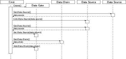
The figur below shows a possible sequence diagram for the initialization:
The figur below shows a possible sequence diagram for a distribute call:
Participants
Data Source
defines an interface for getting parameters
delegates eventually the request to other data sources
Data Gate
distributes parameters to various data drains
Data Drain
defines an interface for setting parameters
is often provided by a parameter object
Collaborations
Data Sources can be cascaded to delegate the getting of Parameters. Objects that provide both a Data Source and a Data Drain interface - like Parameter Pots - can be used at both sides of a Data Gate for writing back changed parameters (see Motivation).
Consequences
The FET pattern introduces a level of abstraction to the getting of parameters.
Implementation
The design of a parameter pot is specifically made for Ada 95, which doesn't provide multiple inheritance.
Sample Code
procedure Init is
begin
  ...
  -- create the data flow links
  Link_Data_Source(dialog, ppp);
  Link_Data_Source(data_gate, dialog);
  Add_Data_Drain(data_gate, ppp);
  Add_Data_Drain(data_gate, cpp);
  ...
end Init;
|
Known Uses
Used in OpenCAGE for providing parameters to command objects either from dialogs or from script.
Related Patterns
None.


